Guelfa
Installation manual
Last updating 12th of November 2024
INTRO
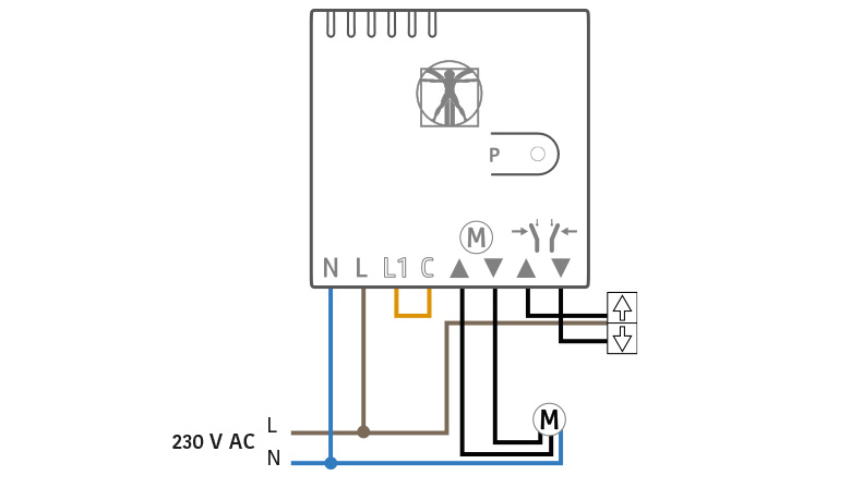
GUELFA is a radio actuator module for roller shutters and shutters. Power supply 220V, inputs for buttons up/ down and outputs for engines, control circuit with interlock . It is compatible with motors and roller blinds.
DESCRIPTION
GUELFA is a radio actuator that allows you to control and to control the shutters, through the app of the system D’AVINCI and the radio control configured for this purpose.It has a range of up to 1000 meters (in free space) by connecting, via radio, directly to the Centrale Lisa or through Automa repeater. The communication is of two-way type (transmission/reception) with the indication of confirmation of receipt and command. The range is reduced in case of obstacles such as walls, objects etc. are encountered.
The communication protocol, like the connections between all components of the system, is the GENIO, encrypted and protected from interception.
The device configuration is done via D’AVINCI app which can be downloaded free of charge from IOS and Android.
The device operates on two frequencies in the 868 MHz band and it is positioned in a automatic and dynamic manner free or less interference.
The device operates on two frequencies in the 868 MHz band, automatically positioning dynamically the one that is freely or less interfered.
DEVICE CONFIGURATION IN THE D’AVINCI SYSTEM
Warning. Before adding a device:
- Install the app D’AVINCI, available for iOS / Android, on your smartphone.
- Create a account . Add a D’AVINCI control panel, save the necessary settings and create at least a room.
- Make sure the Control Panel is turned on and has Internet access via Ethernet.
- Make sure that the Control Panel is off and not running updates by checking its status via the mobile application.
To add a device to the Control Panel, in the D’AVINCI app 1
- Select the tab Device 2

- Click on Add Device

- Assign a name to the device
- Insert the serial number of the device shown on the label or click on icon
 to scan the code via the app.
 - Select the associated Room for the device.
- Click on Add a countdown will start
- Power the device.
The module light will start flashing red.
When paired with the control panel , the indicator lamp will turn flashing green (every 3 sec) and the actuator will appear in the device list.
The connection request to the Control Panel is transmitted for a short period of time as soon as the device is switched on.
If the connection to the D’AVINCI control panel fails, turn off the detector for 5 seconds and repeat the procedure.
1 Installer privileges are required
2The device must be located within the radio communication zone of the associated Control Panel in order to start the configuration procedure.

Connections

The device is intended for indoor installation only.
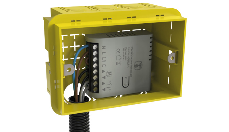
The dimensions of the device allow installation inside standard 503 and 504 junction boxes or in roller shutter housings. It is recommended to use cables with a suitable section to ensure safety and proper operation.
The location of the actuator affects the connection to the Control Panel and any obstacles between devices may block the transmission of the radio signal.
Such obstacles can be walls, floors or large objects within a room.
- In unprotected areas or premises (outdoors).
- Near metal objects or mirrors that may attenuate or block the radio signal.
- Next to other radio devices (gsm/wireless router/etc.) to avoid mutual interference
- In environments where temperature or humidity values may exceed the limits specified in the Technical Specifications.
SETTINGS
The detector settings can be changed in the D’AVINCI app (Installer privileges are required):
- Access the Devices tab
- Select the device from the list.
- Go to settings by clicking on the icon (gear)
DEVICE NAME
Actuator name, displayed in the device list and as notification text.
Can hold up to 24 characters
ROOM
Selecting the virtual room to which the device is assigned
The environment name appears in notifications.
* Changing this parameter requires Administrator privileges
ACTIVATION MODE CONTACT
Set the relay operation mode:
– bistable
– impulsive
Pulse duration (sec) [1 – 240] seconds
RESTING STATUS CONTACT
Set contact status at rest, with non-excited relay:
– Normally open
– Normally closed
SETTING NOTIFICATIONS
Enable/disable notifications for the following events:
– Open/Closed manually
– Automatic opening/closing
USE FOR SWING BLINDS
– YES
Lamella opening time [0.2 – 10.0]
– NO
OPENING TIME: [30 – 120] secconds
CLOSING TIME: [30 – 120] seconds
REPEATER USAGE
Enables the connection of to the system through a repeater, eg Automa.
Repeater number: indicates the number the detector is associated with.
VERIFY RADIO CONNECTION
Enables alarm warning in case of failure to communicate with the
central. If disabled, the report of failure to connect to the central will be
exclusively archived.
Ping interval: time interval, in seconds, between a transmission of
survival and the next in the absence of activation.
– [ 12 : 600 ] seconds
Ping number: number of connection attempts before failure report
radio communication
– [ 1 : 15 ]
RADIO SIGNAL INTENSITY TEST
With this function, the device after pressing the START button processes a test where it will indicate the signal level , flashing n times depending on the result obtained (1-4)
CALIBRATION
After the actuator is installed and connections to the roller shutter motor are made, calibration is recommended. This operation automatically calibrates the opening and closing intervals of the motorized roller shutters.
To activate it press the Start button , and the home automation module will perform a series of operations to detect the correct parameters , in particular, the module will make a series of openings and closures of the roller shutter. The system will collect the data necessary to determine the optimal limits of opening and closing time.
Calibration takes no more than three minutes. Since the calibration performs a sequential automatic movement (up and down of the cover) in case of emergency, the installer can immediately stop the calibration by pressing any button of the local controls or by pressing the dedicated button in the app.
EXCLUDE DEVICE
No: the device works normally and transmits all events/alarms
Total: The device does not execute the sent commands. The system ignores the
device and its notifications.
REMOVE DEVICE
Removes the device from the control panel and deletes the settings.
INTENSITY GENIO SIGNAL
To display the signal strength select the card Devices ![]() and the signal level field GENIO
and the signal level field GENIO
0 = No radio signal, no connection to control panel.
• = Poor radio signal, unstable connection with the Control Panel , operation of the detector not guaranteed.
• • = Low radio signal, low signal strength.
• • • = Good radio signal, good signal strength.
• • • • = Excellent radio signal, optimal signal strength.
Check the radio signal strength before the final installation of the device. In case of low or unstable signal it is recommended to use the Automa repeater.
DEVICE STATUS
To view the status:
- Access the D’AVINCI application
- Select the Control Panel on which the detector is associated
- Go to Devices tab

- Select the detector
| Icon | Description | Note |
 |
Connection Status | - Online : connection established with the control panel
- Offline : connection error with the control panel |
 |
Genio Level Signal | - 1
- 2 - 3 - 4 |
 |
Shutter status | - 25%
- 50% - 75% - 100% |
 |
Lamellas Status | - Close
- Open |
 |
Exclusion device status | - No
- Entirely - Lid only |
 |
Repetear use | - NO
- YES (1-5) |
OPERATION
To control the/and roller shutter/, there are three possible ways:
1. Control via local buttons (UP AND DOWN)
• Manual adjustment: Press and hold the GO or GO button to open or close the roller shutter and stop it in the desired position.
• Open/close completely: Press the button briefly to open or close the roller blind completely.
2. Control via D’AVINCI APP:
From the App select “Commands”:
The list of shutters and scenarios will appear if scheduled.
Position yourself on the roller blind you want to control:
• Open and close total/partial: press Edit and use the selector to set either partial (25% – 50% – 75%) or full opening or closing. Press then, Confirm.
• Adjustable slats: If the roller shutter has adjustable slats, you can adjust them directly from the app.
3. Control via radio control
Use the two lower left and right buttons at the bottom of the remote control if it has been properly programmed to run scenarios.
Note: In case of 230V power failure the first command may not be correct
Scenarios
This function allows us to activate several actions in sequence with a single command.
With the Guelfa module for roller shutters it is possible to set specific scenarios to control openings/closures of one or more roller shutters.
Proceed to settings as for other scenarios taking care to insert appropriate delays between a command and another to avoid that, in the case of commands related to actions of opening/closing of several shutters with a single scenario these occur sequentially to avoid excessive load on the electrical network. Refer to the absorption of individual roller shutters and the availability of sufficient capacity.
For example you can set the scenario “close all shutters” and You will enter the commands of the individual shutters, interspersed with appropriate delays, as well as other scenario “open all shutters” and proceed in the same way.
The activation of the scenarios will be done by the App or by radio control, if appropriate programmed defining, for example that with the button on the bottom left you execute the scenario “close shutters” and with the button on the bottom right you execute the scenario “open shutters”.
It is possible to program that the scenario will be implemented automatically, for example when the system is inserted or deactivated.
In the devices section, press the Control Panel box to access system states.
Press the settings icon in the top right.
Press the Scenarios button.
Press Add Scenario to create a new Scenario. The Created Scenario button will appear with the enable button.
Press the name of the Scenario, to access the programming and add the actions that compose it
WARNINGS AND MALFUNCTIONS
The warning and malfunction indication features are enabled in the device settings, by selecting the warning field
| Indication | Event |
| RED led flashing | Device unpaired Missing radio link |
| GREEN led | Dismount command activated |
| RED led | Ascent command activated |
| ORANGE led | Command activation Automatic regulation/Calibration |
| Green Led Flashing 3 sec | Normal operation |
* Only visible in Calibration mode
The indications refer to the LEDs on the electronic card
TECHNICAL SPECIFICATIONS
| Type of sensor | Radio relay module |
| Self-consumption | < 1 W |
| Implementation capacity | 10^6 actuations |
| Radio communication protocol | Genio |
| Operating frequencies | 868.20 MHz 868.95 MHz |
| Rf signal power | 13 dBm |
| Modulation | GFSK |
| Radio signal range | Up to 1000 m |
| Power supply | 230 VAC |
| Permissible Load | 500 W |
| Installation | Indoor |
| Protection class | IP 20 |
| Operating temperatures | From -5° C to +45° C |
| Maximum permissible humidity | Up to 75% |
| Dimensions | 51x57x18 mm |
| Weight | 45g |
CERTIFICATION
Copyright 2023 - 2024 – D’AVINCI Security Products Srl – C.F. e P.IVA 12908830966 – All right reserved. || privacy policy | cookie policy |

