Lisa
Installation manual
Last updating 05th of November 2024
INTRO
LISA is the alarm control panel, the basic element of the D’AVINCI wireless security system. It dialogues with the sensors from which it receives the alarm and status signals, and the domotic actuators. It dialogues with smartphones, on which the app is installed, through the D’AVINCI Cloud using four vectors: Lan network, Wi-Fi, GPRS 4G and voice channels of the GSM network, so as to ensure security and redundancy of the carrier.
In the event of a lack of the Internet, the Lisa Centre sends calls to scheduled telephone numbers and pre-recorded messages. Dialogue with Control Panels via Internet via LAN, WI FI or GPRS 4G.
The programming and configuration of the Lisa control panel and the peripherals (sensors, sirens, actuators, etc.) is carried out via the D’AVINCI app on smartphones in a simple and intuitive way, the D’AVINCI app works via D’AVINCI Cloud.
CONFIGURATION TO THE D’AVINCI SYSTEM
The Lisa alarm control unit is configured and controlled through the D’AVINCI app, available for professionals and users on Android platforms.
The settings of the users of the D’AVINCI system and the parameters of the connected devices are stored locally on the Control Unit and archived on the proprietary D’AVINCI Cloud.
This mechanism increases the reliability and redundancy of the data.
To set up the system, you need to install the D’AVINCI app and create an account. A single account can manage multiple control units and therefore multiple systems, it is not necessary to create a new account for each control unit.
D’AVINCI Account Creation
The configuration of the entire security system is carried out through simple steps on the app installed on your smartphone.
First download the D’AVINCI app on your smartphone from the App Store or Google Play Store, depending on whether you use iOS or Android. Then create an account by following the wizard. The procedure requires you to confirm your email and mobile phone number.
Control Panel Installation
Before proceeding with the installation of the control panel, make sure that the chosen position is optimal and complies with the requirements.
Make sure that the communication between the control panel and the devices connected to it is stable, otherwise use the Automa radio repeater.
Installation must be carried out by qualified technical personnel. It is recommended to follow the general safety regulations relating to devices connected to the electrical network.
The power supply to the control unit must be separate and must be taken directly from the main electrical panel of the location.
The power supply line must be protected by sectioning and protection devices in compliance with current legislation.
The control unit must be connected after a dedicated interrupting device.
The installation location influences the connection to the sensors and potential obstacles between the devices can block the transmission of the radio signal.
These obstacles can be walls, floors or large objects within the environment.
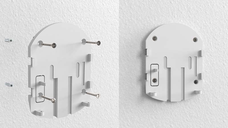
How to install the device:

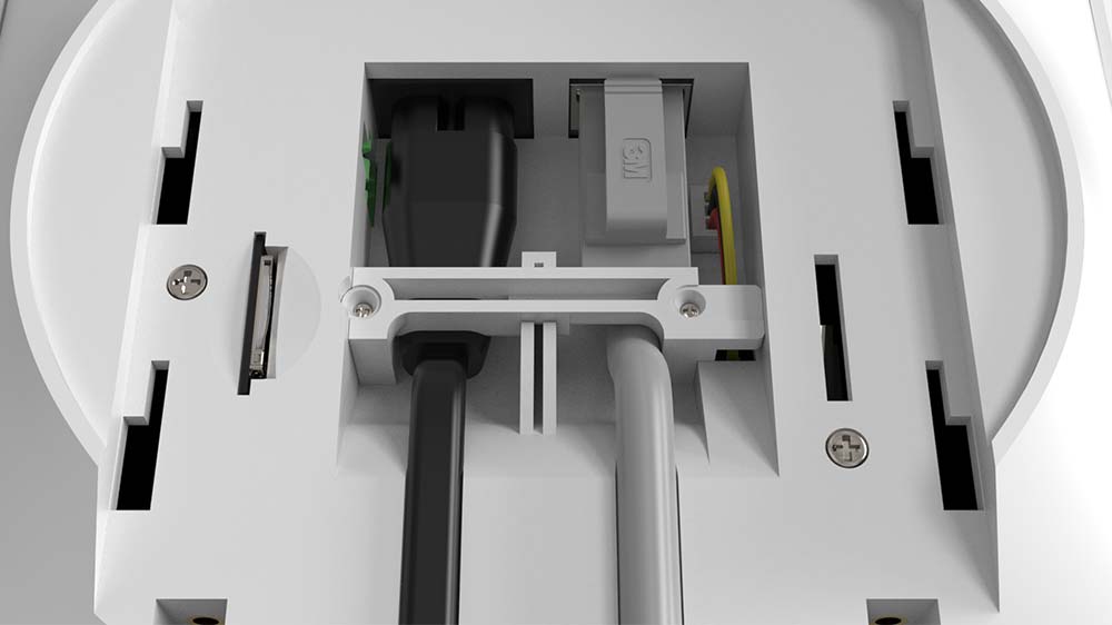
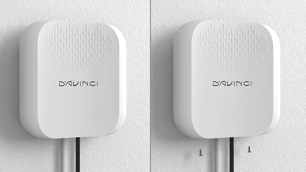

When the control unit is turned on, the LED inside the logo will turn the Italian tricolour, this indicates that the control unit is in operation.
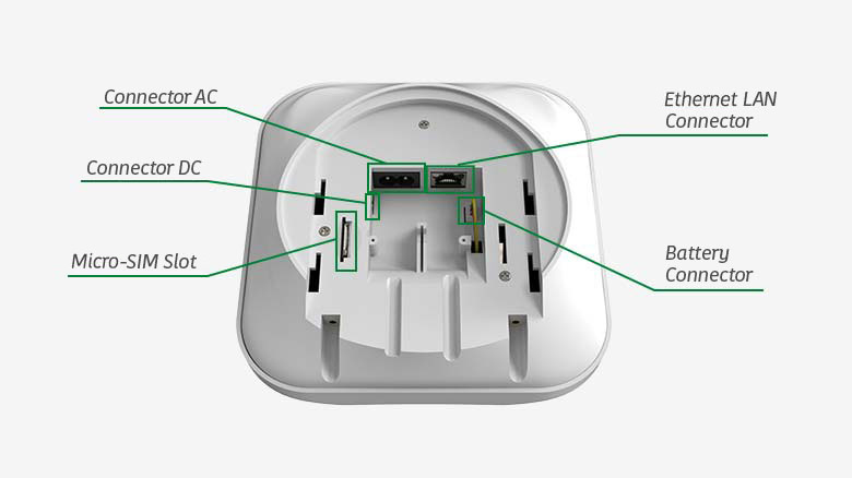
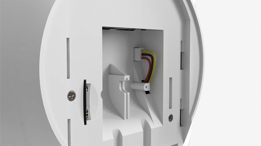
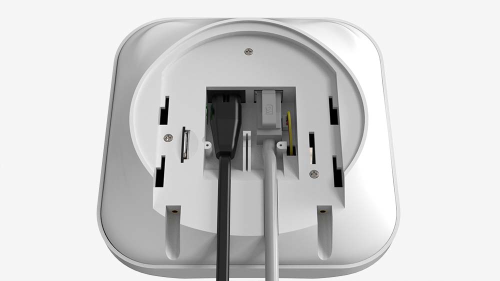
Connect the internal battery plug and power the control unit using the 220 VAC cable supplied, in alternative to a 12 VDC source with a capacity sufficient to allow its autonomy.
The battery will recharge automatically.
ATTENTION: Do not install the control unit:
- In unprotected areas or rooms (outdoors);
- Near metal objects or mirrors that could attenuate or block the radio signal;
- Next to other radio devices (GSM/wireless router/etc.) to avoid mutual interference;
- In environments where temperature or humidity values may be higher than the limits indicated in the technical specifications.
LED SIGNALS
The control panel LED characterizes the system status or events that occur. The D’AVINCI logo on the front of the control unit can light up red, white, green depending on the status.
When there are no signals in the system (no alarm or malfunction) the LED displays the STAND-BY status of the control unit showing the tricolor of the Italian flag in honor of the D’AVINCI GENIO.
| Indication | Event |
| The three LEDs relating to the D'AVINCI logo lit steadily in the white - green - red sequence | Regular status and system not armed |
| The complete D'AVINCI logo in fixed red mode | System status armed |
| The complete D'AVINCI logo in fixed blue mode | System status armed in Stay mode |
| Left green LED off | Control unit not connected to the D'AVINCI Cloud |
| Flashing green LED on the left | Central connected to the D'AVINCI Cloud |
| LED and on the left green on in steady mode | Regular connection to the D'AVINCI Cloud |
| White LED(in central position) flashing | LTE module fault (SIM not inserted, network search) |
| White LED(in central position) in fixed mode | Regular cellular connection (regular LTE module) |
| Yellow LED(in central position) in fixed mode | Connection to the Cloud through the backup vector, LTE module |
| Flashing red LED on the right | Radio fault associated devices |
| Right red LED in fixed mode | Regular status of associated devices |
| Green LED when the control unit is turned on | The control unit looks for the connection with the cloud and after that all three tricolour LEDs light up |
| Short flashing, every three seconds, of the green, white and red led | System disarmed with AC loss |
| Short flashing, every three seconds, of all the red LEDS | System armed with AC loss |
| Short flashing, every three seconds, of all the blue LEDS | System armed in Stay mode with AC loss |
Rooms

Before connecting a device to the system, create at least one Room.
Rooms are used to group devices. The device and the room name will appear in the security system event or alarm text in the notifications section.
To create an room in the D’AVINCI app1
- Select the Rooms

- Click Add Rooms

- Assign a name to the rooms and possibly add an image or take a photo of the room
- Press the Save button
To clear the room or change its characteristics, go to the room settings by tapping the gear icon.
1 Installer privileges are required.
CONNECTING THE DEVICES
After adding the control unit to your account, you can associate new devices to the system
To add a device to the Control Panel, in the D’AVINCI app
- Select the Devices2

- Clic add device

- Assign a name to the device
- Enter the device serial number shown on the label or click on the icon
 to acquire the code via app
 - Select the Room to which to associate the device.
- Press the Add button.
- Power the device.
1 Installer privileges are required.
2 To start the configuration procedure, the device must be within the radio communication area of the associated control unit.
The detector connected to the Control Panel will appear in the list of Devices in the D’AVINCI app.
The detector can be associated to only one control panel.
When connected to a new control panel, the detector stops sending commands to the previous control panel.
N.B.: The new acquisition phase does not remove the detector from the list of devices of the previous control unit. This operation must be carried out manually through the D’AVINCI app.
Operating settings
The system settings can be changed in the D’AVINCI app:
- Access the Devices

- Select the control unit from the list
- Go to settings by pressing the gear icon
 .
.
IMAGE
It is possible to add a personalized image for the D’AVINCI control unit. It is displayed in the selection menu and helps to identify the system.
To change or set the image, press the camera icon and set the desired image.
To change or modify the image, press camera icon ![]() and set the desired image
and set the desired image
NB: Changing this parameter requires Installer privileges
DEVICE NAME
It appears in the devices section and in app notifications. The name can contain up to 24 characters.
To change it, press inside the field and enter the new name.
NB: Changing this parameter requires Installer privileges
ETHERNET
- Enable the connection via ethernet.
- Connection Type
-DHCP
-STATIC: Manually enter IP addresses
CELLULAR NETWORK
- Enable the SIM:This function allows the control panel to communicate with the cloud via the SIM, when the LAN and Wifi are absent.
- Enable connection via cellular network:This allows us to make voice calls and text messages via the SIM when the LAN and Wifi are absent. The necessary parameters are acquired automatically once you leave this window.
WIFI
Enable the connection via WIFI
With the update button, a scan will be made of the networks found and the most suitable one will have to be selected according to the signal level.
AREAS
They represent a subset of the system and allow you to:
– manage rooms or groups of devices separately;
– limit access to control security modes.
SURVEILLANCE CENTER
It allows us to connect the control panel to a monitoring institute by choosing between two transmission protocols:
– (SIA-DCS)
– (ADEMCO-CID)
Choose the reporting channel:
– Ethernet/Wifi
– GPRS
Primary and secondary IP address, and central surveillance monitoring interval (1-24 hours).
Posssibility to Enable the Encryption and the mode of sending the alarm reset.
SETTINGS
– Integrity system check:
It allows us to check the status of the devices or the control panel during the insertion , warning of any anomalies, alarms and open areas. We can allow forced insertion by activating the ‘Allow Insertion’ function.
– VARIOUS:
– Automatic deactivation of devices:
You can disable tampering on the control panel
You can activate the siren on the tamper of control panel
You can choose a time after which the control panel notifies us the power grid failure
You can choose the time of self-exclusion of any bistable devices in alarm (0-60 minutes)
TIME ZONE
Choice of time zone
SCENARIOS
They allow us to program a set of actions grouped in a single command. With Scenarios it is possible to:
– choose the type of action (arming, disarming, activations, deactivations);
– choose whether to enable Stay mode;
– how many and which Areas to insert in the scenario
– create a time scheduler
USERS
This section allows you to invite or remove users.
By selecting the individual user, it is possible to define the permissions and associated areas.
INSTALLERS
This section allows you to invite or remove installers.
MANUAL
This section displays the alarm control unit manual.
SYSTEM DISSOCIATION
Removes the account from the system. The settings and connected devices remain configured in the alarm control unit.
System status
The status shows information and operating parameters of the device.
To view status:
- Access the D’AVINCI application
- Select the system to which the detector is associated
- Access the Devices

- Touch the detector box
| Icon | Description | Note |
| Connection status | - Online : connection established with the control panel
- Offline : connection error with the control panel |
|
| Tamper Status | - Irregular: Central removed from mounting bracket
- Regular: the power station cover is closed | |
| Electrical network status | - Network disconnected
- Network connected | |
| Battery level |
- 25 % - 50 % - 75 % - 100 % | |
| Ethernet status | - Enabled and unused
- Connected - Disabled |
|
| Wifi status | - Approved and unused
- Connected - Disabled |
|
| Cellular status | - Enabled (only calls/sms)
- Connected - Disabled |
|
| Average noise (dBm) | Power level at control panel installation site. Installation of the control panel with high noise levels may cause loss of connection to associated devices or notifications of tampering attempts |
Replacing the batteries
If the control unit’s battery is low, the user receives a notification via app.
Keep the control unit case clean by removing dust, cobwebs and other impurities. Use a soft, dry cloth for maintenance operations on the equipment, avoid using substances containing alcohol, acetone, petrol or other active solvents.
TECHNICAL SPECIFICATIONS
| Type | Wireless control panel 868 MHz; WIFI + Ethernet module and 4G LTE communicator |
| Power supply | 230 V AC / 12 V DC
Built-in backup battery: Li-Ion 3000 mАh |
| Manageable wireless devices | Up to 200 |
| Radio range | Up to 1500 meters in open space |
| Sirens | Max 6 |
| Users allowed | Max 200 |
| Rooms | Max 30 |
| Repeaters | Max 5 |
| Encryption | Proprietary protocol based on AES |
| Anti-sabotage protection | - antijammer
-anti-tampering (anti-tear) and anti-opening tamper |
| Radio communication protocol | Genio |
| Operating frequencies * | 868.00 MHz 868.20 MHz 868.60MHz 868.95MHz 921.00 MHz 921.20 MHz 921.60 MHz 921.80 MHz *based on the sales region |
| Communication channels | Ethernet; Wi FI (802.11b/g/n); 4G LTE; 2G Voice |
| Sim card supported | Micro SIM | Installation | Indoor |
| Protection class | IP40 |
| Operating temperatures | from -10°С to +40°С |
| Maximum allowable humidity | up to 75% |
| Dimensions | 170x165x50 mm |
| Weight | 437 grams |
CERTIFICATION
Copyright 2023 - 2024 – D’AVINCI Security Products Srl – C.F. e P.IVA 12908830966 – All right reserved. || privacy policy | cookie policy | Policy D'AVINCI Cloud

