Visus
Installation manual
Last updating 12th of May 2025
INTRO
VISUS outdoor is a wireless volumetric video detector DT( 2IR+MW +CAM) with integrated camera. It works for up to 5 years with pre-installed batteries and it is equipped with infrared capable of detecting intruders within a radius of 12 meters with installation height of 1.2 m. Camera viewing angle 110° horizontally and 70° vertically. It is equipped with video recording function through D’AVINCI App where on request, 3/5 frames are sent. It is ideal for protecting outdoor areas such as gardens, terraces, garages, etc.
OPERATION
VISUS outdoor is part of the D’AVINCI system,with a range up to 1500 meters (in free space) connecting, via radio, directly to the Lisa control panel or through the “Automa” repeater. The communication is of two-way type (transmission/reception) with the indication of confirmation of receipt and command. The range is reduced in case of obstacles such as walls, objects etc. are encountered.
The communication protocol, as well as the connections between all the components of the system is GENIO , which is encrypted and protected from interception. Anti-blinding on PIR (lower and upper IR section).
Three-level IR sensitivity configuration, alarm LED.
After detecting movement, the integrated camera takes a series of photos, which allow you to check the alarm and notify to the Surveillance center if necessary.
The detector operates on four frequencies in the 868 MHz band, positioning itself automatically and dynamically on that is free or not interfered.
PHOTO VERIFICATION
The detector has an infrared illumination to take photos in the dark that activates automatically in case of low light.
There are two types of photo-check: alarm photos, photos on request:
1. Photo for alarm
The alarm signal of Globo Cam can be accompanied by an image or a series of photos in the D’AVINCI App. The detector takes one or more pictures when the control unit is in insertion mode.
Photos can be viewed in the app as images or animated photo series (if more than one photo is taken). The number of images acquired is set in the D’AVINCI App. To view the photos you received, click on the corresponding Globo Cam notification in the event log.

The On-demand photo function allows users to take photos with the built-in camera of the detectors. With this function, you can check the situation on the system, for example: check what children are doing or pets are doing or just what is happening at home.


DEVICE CONFIGURATION IN THE D’AVINCI SYSTEM
- Install the app D’AVINCI, available for iOS / Android, on your smartphone.
- Create a account . Add a D’AVINCI control panel, save the necessary settings and create at least a room.
- Make sure the Control Panel is turned on and has Internet access via Ethernet.
- Make sure that the Control Panel is off and not running updates by checking its status via the mobile application.
To add a device to the control panel, in the D’AVINCI app 1
- Select the Tab Device 2

- Click on Add Device

- Name the device
- Insert the serial number of the device shown on the label or click on icon
 to scan the code via the app
 - Select the associated Room for the device
- Click on Add – a countdown will start
- Turn on the device by pressing the ON/OFF button on the back (see installation phase of the device).
The detector top pir light will start flashing red. When paired with the control panel, the detector will appear in the list of devices in the D’AVINCI app.Then it will be necessary to close the tamper, placing it on its bracket, this to allow you to carry out the calibration phase, with the 2 yellow blinking LED of the upper pir and lower pir, for about a minute. After that, the lights will turn off and the device will be ready to detect movements and transmit them to the control panel.The connection request to the Control Panel is transmitted for a short period of time as soon as the device is switched on. If the connection to the D’avinci control panel fails, switch off the detector for 5 seconds and repeat the procedure.
1 Installer privileges are required.
2 To start the configuration procedure, the device must be within the radio communication zone of the associated Control Panel.
DETECTOR INSTALLATION
Make sure that you have selected the ideal installation location according to the guidelines in this manual.
The installation location of the sensor affects the connection with the control panel and any obstacles between the devices can block the transmission of the radio signal.
PRE-installation


To install the device:


Adjust, the position of the PIR cursor to the desired range level and then turn on the device using the appropriate button, proceeding with pairing, via app, with the control panel.


After choosing the desired position, tighten both screws with a cross screwdriver, first the upper one and then the lower one.


Side view

Top view

Rotation
– In areas with a strong presence of tall plants that can disturb the detector with the wind.
– Next to other radio devices (gsm/wireless router/etc.) to avoid mutual interference
– In environments where the temperature or humidity values may exceed the limits specified in the technical specifications
OPERATING SETTINGS
The detector settings can be changed in the D’AVINCI app (Installer privileges are required):
- Go to device tab

- Select the device from the list.
- Go to settings by clicking on the icon

DEVICE NAME
Detector name, displayed in the device list and as notification text. It can contain up to 24 characters.
ROOM
Selecting the virtual room to which the device is assigned the environment name appears in notifications.
Note: Changing this parameter requires Administrator privileges
METHOD OF ALARM
It shows how the detector reacts to alarms.
– Instantaneous: the detector, when the system is in place, immediately signals the alarm.
– Delayed: the detector, with the system inserted, signals the alarm after a time counter (see input/ output delay).
Input delay: 5 to 120 seconds.
Entry delay is the time that the user has to disconnect the system after entering the protected area.
Output delay: 5 to 120 seconds.
Exit delay is the time that the user has to leave the protected area after insertion.
– Continued: The detector adds input/output delays of devices that detected an alarm before it. When activated individually, it immediately triggers the alarm
STAY MODE ARMED
Pairing the detector to night mode. This type of insertion allows, for example, to insert the perimeter area and allows people to move freely in other areas.
- Input delay in stay mode: 5 to 120 seconds.
Entry delay is the time that the user has to disconnect the system after entering the protected area. - Output delay in stay mode: 5 to 120 seconds.
Exit delay is the time that the user has to leave the protected area after insertion.
ALWAYS ACTIVE
If this option is enabled, the detector is always armed, detects the alarm condition and sends the signal to the Control Panel.
SENSITIVITY
Motion detector sensitivity level (infrared)
– High
-Normal
-Low
MW REGULATION
Adjusts the microwave level [ 25%, 50%, 75% 100%]
TIME OF INHIBITION
time interval when the sensor does not detect the alarm condition
– None
– 30 seconds
-1 min
-2 min
ENABLE MASK
Enables/disables the anti-masking function
EXCLUSION MW
Enables/disables the microwave sensor.
– Never
– Alarm off : green active functionality (disables emissions)
– always
SOUND ON THE ALARM
It allows you to activate the siren in case of alarm signal, if the system is armed
SIREN ON WITH LID OPEN
It allows you to activate the siren in case the detector is in the tamper state (tamper anti-opening or anti-tampering open).
ACTIVE SIREN IN MASK
Activates the siren in case of masking signal.
NUMBER OF ALARMS FOR SELF-EXCLUSION
Allows you to enter the number of alarms for the detector, during the same insertion, which cause the automatic exclusion of the detector. The detector will be automatically included the next time the system is inserted.
– Disabled
– 3 , 6, 9, 12 , 15.
IMAGE RESOLUTION
– 320 x 240 px
– 640 x 480 px
OPTIMIZE PHOTO UPLOAD TIME
If enabled, it allows the reduction of the time for receiving images at the expense of a slight decrease in the quality of the same photos sent.
ALARM PHOTOS
– None
– 1, 2, 3, 4, 5 (max 3 photos 640x480px)
PHOTO CONFIRMATION ALARMS
– All
– 1, 2, 3, 4, 5, 6, 7
PHOTO ON REQUEST
– None
– 1, 2, 3, 4, 5 (maz 3 photos 640×480)
WARNING LAMP
Enables the light indication for the alarm signal.
– only test operation
– always
REPEATER
Enables the connection of to the system through a repeater, eg Automa.
– Repeater number: indicates the number to which the detector is associated.
VERIFICATION OF RADIO CONNECTION
Allows you to enable the alarm in case of failure to communicate with the Central. If disabled, the report of failure to connect to the Central will be stored exclusively.
PING INTERVAL
Time interval, in seconds, between one survival transmission and the next in the absence of activation.
[ 12: 600 ] seconds
NUMBER OF PING EXPECTED
Number of connection attempts before radio failure report
[ 1 :15 ]
RADIO SIGNAL INTENSITY TEST
With this function, the device after pressing the START button processes a test where it will indicate the signal level , flashing n times depending on the result obtained.(1-4)
DETECTION TEST
With this function, the device after pressing the START button directly from the App will enter the test mode, keeping the red LED always on and every movement within the coverage area, the red LED will turn off to signal a movement. Refer to the “Warnings and Malfunctions” table for visual activation indications of each individual IR/MW stage
EXCLUDE DEVICE
No: the device works normally and transmits all events/alarms.
Total: The device does not execute the sent commands. The system ignores the
device and its notifications.
Tamper Only: The system ignores notifications regarding activation of the device’s tamper button (tamper).
REMOVE DEVICE
Dissociate the detector from the Control Panel, removing it from the app and deleting the device settings.
PHOTO RECEPITION SETTINGS
SET UP PHOTOS ON REQUEST
A technical user with access to the settings can, by selecting “Photos on demand”, set:
– Up to 5 frames per 320×240 px resolution
– Up to 3 frames per 640×480 px resolution
*After you have selected the number of frames, go back to confirm that you have programmed them.

SET UP PHOTOS FOR ALARM
A technical user with access to the settings can, by selecting “Photo for alarm”, set:
– Up to 5 frames per 320×240 px resolution
– Up to 3 frames per 640×480 px resolution
*After you have selected the number of frames, go back to confirm that you have programmed them.

INTENSITY GENIO SIGNAL
To display the signal strength select the card Devices ![]() and the signal level field GENIO
and the signal level field GENIO
0 = No radio signal, no connection to control panel.
• = Poor radio signal, unstable connection with the Control Panel , operation of the detector not guaranteed.
• • = Low radio signal, low signal strength.
• • • = Good radio signal, good signal strength.
• • • • = Excellent radio signal, optimal signal strength.
Check the radio signal strength before the final installation of the device. In case of low or unstable signal it is recommended to use the Automa repeater.
DEVICE STATUS
To view the status:
- Access the D’AVINCI application
- Select the Control Panel on which the detector is associated
- Go to Devices tab

- Select the detector
| Icon | Description | Note |
 |
Connection status | - Online: connection established with the control panel
- Offline: connection error with the control panel |
 |
Genio signal level | - 0
- 1 - 2 - 3 - 4 |
 |
Battery level |
- 25 %
- 50 % - 75 % - 100 % |
 |
Tampering status | - Alarm
- Regular |
 |
Antimask status | - Normal : normal operation
- Mask : masking device |
 |
Input primary status | - Regular
- Alarm |
 |
Sensitivity | - High
- Normal - Low |
 |
MW regulation | - 25%
- 50% - 75% - 100% |
 |
Exclusion status device | - No
- Total - Only lid |
 |
Always active | - No
- Yes |
 |
Alarm mode status | - Instant
- Delayed - Continued |
 |
Arming in stay mode | - No
- Yes |
 |
Repeater use | - No
- Yes (1-5) |
REPLACING BATTERIES
The detector periodically checks the status of the batteries and it informs the control panel when they are in a phase of exhaustion. The battery life of the detector depends on the frequency of activation of the detector, the ping interval between the detector and the control panel, the required number of frames and the programming set for the sensor. If the control panel indicates that the battery of the detector is low, the sensor must be replaced quickly.
NOTE: After the low battery signal, the detector does not send photos for both alarm and request.

1. Before opening the detector, set the control panel in test mode to prevent the tamper alarm from being reported;
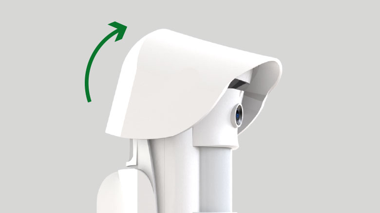
2. Release the visor by applying pressure on the front of the visor;

3. Unscrew the screws securing the detector to the bracket;

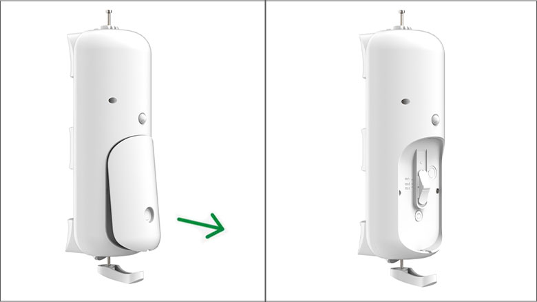
4. Once the sensor has been removed from the bracket, open the door on the back by using a small screwdriver;

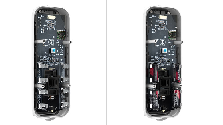
5. Unscrew the 4 screws at the bottom of the device, taking special care not to move the gaskets;

6. Replace all batteries with new CR123A batteries respecting the polarity. We recommend that you install the batteries specified by the manufacturer to ensure that the sensor works. If other batteries are used, the operating time may differ from that estimated by the manufacturer;
7. After inserting the batteries, close and lock with the appropriate 4 screws the bottom of the device paying special attention to the correct insertion of the gaskets and close the flap on the back;

8. Insert the detector on the support and rotate it to the desired position through the reference marks according to the area to be covered;

9. After choosing the desired position, lock the sensor by tightening both screws with a cross screwdriver, first the upper and then the lower;
10. Insert the protective screen, to increase the protection of the product from atmospheric agents;
11. Wait for the detector to finish the initialization phase and then run some functional tests, as indicated in the menu Operation Check .
Integrated batteries can only be removed by qualified personnel. Make sure that the batteries are empty before removing them. For disposal please refer to the instructions in this manual.
WARNING AND MALFUNCTIONS
| Indication | Event |
| Yellow LED bottom on* *visible only in detection test mode |
IR stage activation |
| Yellow LED top on* *visible only in detection test mode |
IR stage activation |
| Green LED on* *visible only in detection test mode |
MW stage activation |
| Red LED on | Alarm signal |
| YELLOW LED PIR upper and lower
short alternating flashing every sec. |
Antimask phase initialization and calibration |
| RED LED short alternating flashing every sec. |
Waiting for tamper closure |
- Detector is removed from installation location or detector housing is open (tamper anti-tampering active)
- There is no radio communication between the control panel and the detector
- Detector battery is low
TECHNICAL SPECIFICATIONS
| Sensor type | DT Volumetric outdoor detector with camera (2 IR + MW + CAM) |
| Detector range | Up to 12 meters (with installation height of 1.2m) according to the position of the slider relative to the lower PIR, as indicated MIN:6 m MED:10 m MAX:12 m |
| Anti-sabotage protection | - antijammer
- anti-tampering: - anti-tear - anti-opening |
| Detenction logic | And |
| Sensitivity | Programmable by App |
| Microwave Type | 24 GHz |
| Antimask | Active on Ir section |
| Radio communication Protocol | Genio | Operating frequencies | 868.0 MHz 868.2 MHz 868.80 MHz 868.95 MHz |
| Rf signal power | 13 dBm |
| Modulation tyoe | GFSK |
| Radio signal range | Up to 1500 m |
| Repeater compatibility | From FW 2.0 and HW 2.0 revisions |
| Camera angle view | 110° horizontal ; 70° vertical |
| Frame resolution | 320x240 px or 640x480 px |
| Power supply | 4 batteries CR123A – 3V |
| Battery life | 5 years |
| Height Installation | 1.2 m |
| Protection class | IP55 |
| Operating temperature | from -15°С to +55°С |
| Maximum humidity | Up to 95% |
| Dimensions | 93 x 240 x 126 mm with dome and bracket |
| Weight | 610 g |
CERTIFICATION
Copyright 2023 - 2024 – D’AVINCI Security Products Srl – C.F. e P.IVA 12908830966 – All right reserved. || privacy policy | cookie policy | Policy D'AVINCI Cloud

